The Mysterious MeshGeometry3D Normals Property (Part 2)
December 18, 2006
Roscoe, NY
Yesterday I showed you two square cuboids in a WPF 3D XAML file that had very different types of shading on their surfaces, and I said that this difference basically had to do with the Normals property of the MeshGeometry3D class. If you don't define a Normals collection, WPF will calculate values for you.
Here are two more square cuboids:
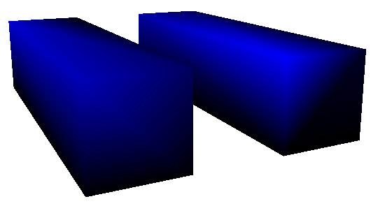
The XAML file is here:
These two figures are defined nearly identically, and they are illuminated by the same DirectionalLight object. But look at the intensity of the upper-left-front vertex of each figure. Using my little WhatColor utility, I read a decimal RGB value of about 0-0-180 on the vertex of the figure on the left, and about 0-0-248 on the figure on the right. That's a significant difference considering that you really have to dig into the file to figure out exactly what's causing it.
As you know, everything in WPF 3D is built up from triangles. Each of the six sides of these two figures consists of two symmetrical triangles that together form a rectangle. There are basically two ways you can make a rectangle from two triangles:
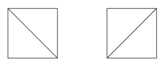
And yes, it makes a difference. In the XAML file, look at the 1st and 3rd lines of the two TriangleCoordinates collections. The first line indicates the indices within the Positions collection of the coordinates of the two triangles that comprise the front face of the square cuboid. The third line of the TriangleCoordinates property involves the top face. These triangles are defined differently in the two figures, and that difference is what causes the difference in the intensity of that upper-left-front vertex.
When the WPF 3D system renders each triangle, it must determine how much light is reflected from that triangle. For DirectionalLight, the calculation is based on the angle the light makes with the figure. This calculation requires the determination of a vector perpendicular to the surface of the figure, called a normal vector. This normal vector is fairly easy to calculate: The three vertices of the triangle define two vectors, and taking the cross product of those vectors yields the normal vector. The amount of reflected light is then proportional to the negative cosine of the angle between the normal vector and the direction of the light. (If the normal vector and the light-direction vector are both normalized, then this is the same as the negative dot product.)
For example, look at the second figure on the right from yesterday's blog entry. The DirectionalLight has a Direction vector of (2, -4, -1). The normal vector of the front face of the square cuboid is (0, 0, 1). The negative cosine of the angle between these vectors is 0.22. Therefore the front face reflects 22% of the directional light. (Because the brush is blue, only blue light is reflected.) 22% of 255 is 56. Add 64 for the AmbientLight. The front face should have an RGB value (in decimal) of 0-0-110, and WhatColor says that it's actually 0-0-109.
That's the case for individual triangles, or when multiple triangles form a flat surface (as in the second figure from Saturday's blog entry). When multiple triangles meet at common vertices at angles, it gets considerably more complicated. Basically, WPF 3D calculates a normal for each vertex of the figure. Vertices don't seem to have normals, but the WPF calculates a vertex normal as an average of all the normals of all the triangles that meet at that vertex. Then, for each point within the triangle, the reflected light is an interpolation of the reflected light at the three vertices of the triangle.
For example, consider the upper-left-front vertex of the first figure from today's XAML file. Four triangles meet at that vertex — one from the left face, one from the top face, and two from the front face. The normal vectors of these faces are, respectively, (-1, 0, 0), (0, 1, 0), and two times (0, 0, 1), for a total of (-1, 1, 2). The DirectionalLight vector is (2, -4, -1). There is no ambient light. The negative cosine of the angle between (-1, 1, 2) and (2, -4, -1) is 0.71, and 71% of 255 is 181, so the RGB color of that vertex should be (in decimal) 0-0-181. That about matches what I found empirically.
In the second figure, four triangles again meet at that vertex — one from the left face, two from the top face, and one from the front face. The normal vectors are (-1, 0, 0), two times (0, 1, 0), and (0, 0, 1) for a total of (-1, 2, 1). The negative cosine of the angle between (-1, 2, 1) and the DirectionalLight vector of (2, -4, -1) is 0.98, which when multiplied by 255 is 250, for an RGB value of 0-0-250, or about what I found empirically.
Fortunately, everything that's happening here is deterministic and not very complex. Yet, if you don't know how WPF 3D is calculating these vertex normals, it can seem very mysterious and unpredictable. Because the illumination of each point in each triangle is calculated as an interpolation of the illumination of the vertices, sometimes edge enhancement is apparent, and sometimes not. Sometimes bright accented lines cut across the diagonal of a flat rectangular surface, and sometimes not.
What this tells me is that providing an explicit Normals property is crucial if you don't want the illumination of your 3D figures to have the often haphazard results of the default calculation.